Hardware Overview
Technical Specifications
Sensor Specifications
| Sensor | |
|---|---|
| Sensing Width | 160mm |
| Sensing Height | 10-50mm |
| Number of Internal Sensing Elements | 32 |
| Field Measuring Range | 0 – 4 millitesla |
| Sensing Refresh Rate | 200 Hz |
| Number of Simultaneous Tracks | 2 |
| Track Position Sense Resolution | 1mm |
| Track Angle Sense Resolution | 1 Degree |
| Number of Simultaneous Markers | 2 |
| Marker Position Resolution | 0.5mm X and Y |
Communication Specifications
| Communication | |
|---|---|
| USB | Yes |
| RS232 | Yes |
| RS485 | Contact Naviq |
| RS232 Bit rates | 9.6, 19.2, 38.4, 57.6 or 115.2 kbps |
| CANBus | Yes - CANopen |
| CAN Bit rates | 125, 250, 500 or 1000 kbits/s |
| Bus Termination Resistor | 120-ohm internal. Software selectable |
Diagnostic Specifications
| Diagnostics | |
|---|---|
| LEDs | Two RGB LEDs |
| Power-on Self-test | Internal magnetic sensing self-test |
| Self-test | Communication-readable pass/fail, minimum delta, and maximum delta |
Electrical Specifications
| Electrical | |
|---|---|
| Power Consumption | 800mW |
| Supply Voltage | 7V to 28V |
| Reverse Polarity Protection | Yes |
| Inrush Current Limiting | Yes |
| Surge Protection on Com Lines | Yes |
Physical Specifications
| Electromechanical | |
|---|---|
| Power & Signal Connector | M8, 4-pin, Male Connector |
| Dust and Water Protection | IP54 |
| Operating Temperature Range | -40°C to +65°C |
| Certification | Compliant EN IEC 60947-5-2-2020. CE Marked |
| Dimensions | 165mm x 35mm x 25mm |
| Housing Material | ABS |
| Weight | 80g |
Connector and LED Identification
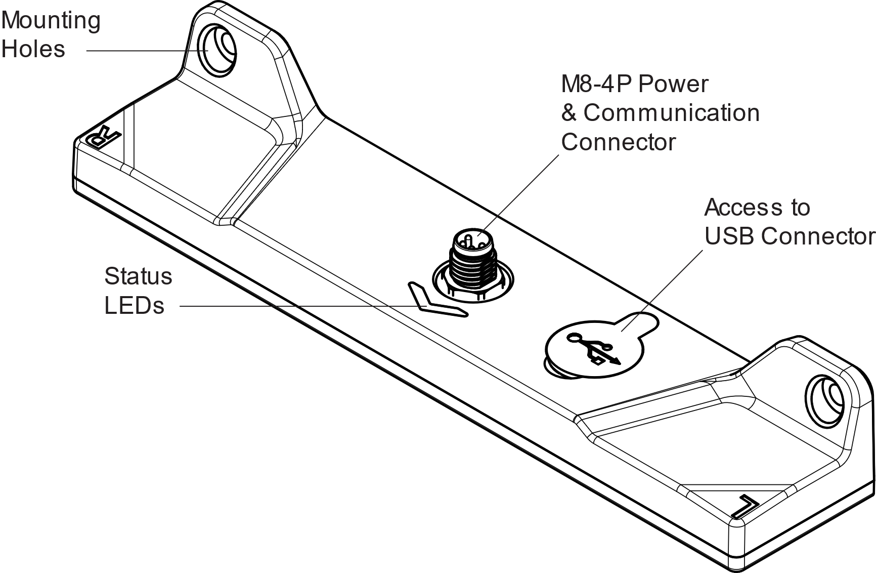
Status LED Patterns
The MTS160 has two RGB LEDs located behind the arrow-shaped window. Current firmware uses these LEDs to indicate zero-calibration state and live track/marker detection. Self-test results are available through the communication interface; they are not latched into a separate red LED fault pattern.
| LED Status | Track Detect | Marker Detect | Description |
|---|---|---|---|
 Blue / Blue Blue / Blue | No | No | The sensor is powered, zero-calibrated, and ready, but no track, markers, or point sources are detected. |
 Green / Green Green / Green | Yes | No | The sensor is detecting a magnetic track, with no markers detected alongside it. |
| Green / Yellow or Yellow / Green | Yes | Yes | The sensor is detecting a magnetic track and one side marker. Use the LM/RM serial fields or CAN status bits for side-specific control logic. |
 Yellow / Yellow Yellow / Yellow | Yes | Yes | The sensor is detecting a magnetic track with markers on both sides. |
| Blue / Yellow or Yellow / Blue | No | Yes | The sensor is not detecting a track, but one marker flag is active. |
| Yellow / Yellow | No | Yes | The sensor is not detecting a track, but both marker flags are active. A standalone point-source magnet without guide tape is commonly reported this way. |
 Steady Purple Steady Purple | — | Sensor is not calibrated. Perform zero-calibration with the Naviq utility. | |
Suitable Magnetic Materials
The sensor is designed for use with magnetic tape that has unipolar magnetization, with either the North or South pole on the top surface. It supports different tape widths and operating heights within the specified sensing range.
WARNING
The sensor will not work with materials that use alternating-pole magnetization.
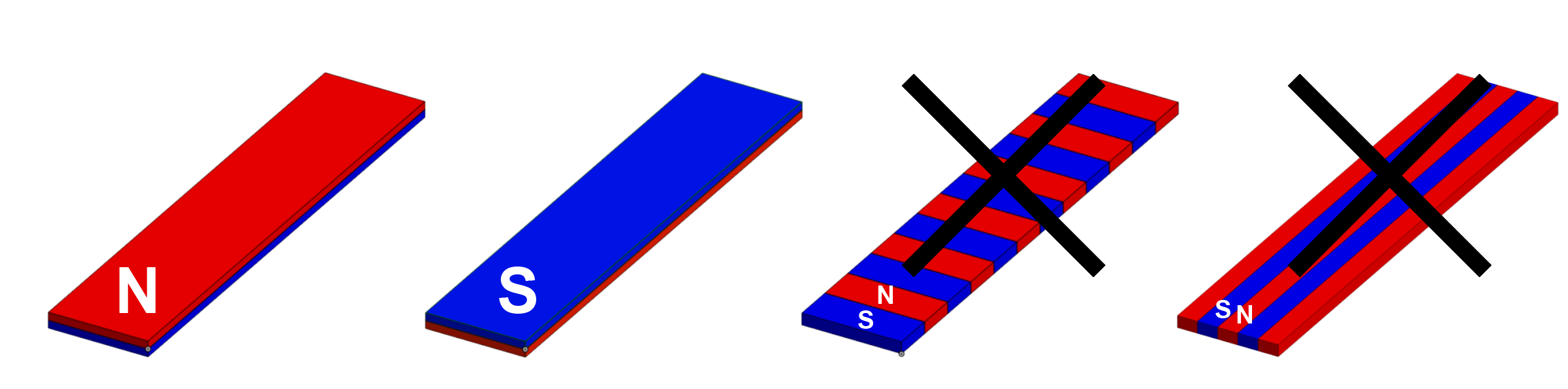
Figure 3 shows examples of magnetic components compatible with the sensor. The graph above each example illustrates the relative field strength and polarity profile.
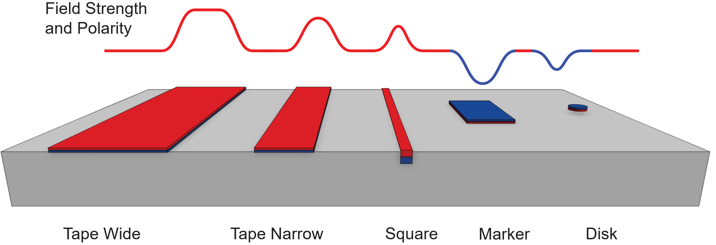
Tracking Tape
Use magnetic tape to define the path for the robot to follow. Tape is commonly available in narrow (25 mm) and wide (50 mm) versions. Wider tape generally produces a stronger magnetic field and has higher adhesion to the floor. The narrow tapes are more economical.
Square Profile
For high-traffic areas or harsh environments, a magnetic square profile embedded in the floor may provide better durability.
Position Markers
Position markers are made from magnetic material with polarity opposite to that of the main tracking tape. They are used to provide location reference points along the track.
Point Source Disks
For precise end-position alignment, 20 mm magnetic disks can be used as localized magnetic point sources. These allow the sensor to determine X and Y position for fine alignment. Point source disks are available from Naviq.
Mechanical Dimensions

All dimensions are in millimeters.
TIP
A 3D Step model of the MTS160 is available at naviq.com